
THOROUGHLY CHECK THE WINDOW UNIT FOR POSSIBLE TRANSIT DAMAGE. DO NOT INSTALL IF UNACCEPTABLE.
Each unit is shipped upside down to protect the vinyl backing under the seat board. The underside of this seat board will be visible from the exterior of the home.
IMPORTANT: CONSULT YOUR LOCAL BUILDING CODES FOR ADDITIONAL INSTALLATION REQUIREMENTS.
The quality of installation will effect the performance of this product. The manufacturer warrants this product when installed per the instructions as described in this document. The manufacturer accepts no responsibility for air or water infiltration above, under or around the window. Painting any vinyl components will null and void all warranties.
TAKE SPECIAL CARE WHILE HANDLING AND STORING YOUR NEW WINDOW UNIT.
To enhance the beauty and protect the durability of the unit’s finish, we strongly recommend this product be protected from exposure to the elements. This window is shipped, and should be stored in an upside down position on a flat, level surface.

• Tape measure
• Level
• Screwdriver to fit supplied bit
• Hammer
• Utility knife
• Sealant gun
• Jack
• Shims
• 10d galvanized finish nails or #8 x 2 ½” flat head screws
• Backer rod
• Flashing membrane
• Exterior-grade sealant
• Low-pressure expanding foam
• Interior trim
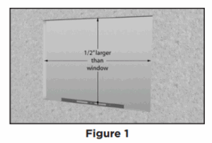
The rough opening must be level, plumb and square and should be ½” larger than the window width and 1/4” larger than window height (Figure 1).
Note: For window units placed in areas with DP ratings higher than DP-35 or where structural insulated panels are used, an independent engineering method of installation may be required. Please consult with your local building inspection office.
If weather-resistant barrier is used, apply per that product manufacturer’s specifications or cut the material as shown in Figure 2.
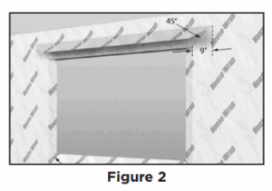
Cut the top left and top right corners at 45° angles, about 9” in length to expose the exterior sheathing above the opening. Cut the bottom corners of weather-resistant barrier at a 45° angle. Fold the bottom and side flaps against the wall and staple to framing. Should a prescribed pan flashing be used, follow the flashing manufactures instructions. Apply flashing membrane across the sill and 6” up each side, overlapping the exterior sheathing by 1”. Apply a second length of flashing membrane, overlapping the first piece by 1” and 6” up each side.
Check the sill plate with a string line to detect high or low spots and shim as necessary. Place shims at the sill, directly supporting the bottom seat of the window unit uniformly at 16” – 18” on center once it is in place.
Set boards on the ground to support the window unit and keep the threaded rod from being damaged against the ground. With assistance, flip the entire window unit over, placing the seat board onto the boards. The cable ends and shipping skids will now be visible on top of the head board. Remove the two pairs of shipping skids by prying them away from the plywood.
Remove the four triangular braces from the four interior corners by prying them away from the plywood. Remove the vertical brace. Remove the vinyl edge protectors from the four sides of the interior edges.
Using scrap lumber cut to size or a sawhorse with blocks on top, temporarily support the unit in place while permanently securing the unit to the framing members of the home. Use a jack to make fine adjustments (Figure 3).

With assistance, insert the unit from the exterior of the building. Place the bottom of the window against the bottom of the rough opening, and slide into the opening until the interior of the unit aligns with the inside wall surface. Center the unit between the vertical framing to allow for shimming later. Slide the temporary support under the seat of the unit.
NOTE: If the exterior is brick or masonry, you must leave a 3/8” gap between the bottom seat of the window and the masonry to avoid “brick binding.”
From the interior, shim and adjust the head board, seat board and both side boards as required to get all four sides plumb and level and the entire unit square inside the opening. Shims must be located 4” from each corner and no more than 16” apart on all four sides to secure the boards from movement.
Note: Pilot holes may be helpful if using screws. Using either 10d (3”) finishing nails or #8 x 2-1/2” flat head screws, drive one fastener at 4” from the head near the top of each side jamb and one fastener at 4” from the seat near the bottom of each side jamb. The fasteners should penetrate through the plywood jamb and shims, and then into the rough opening framing members.
Do not remove the temporary support yet!
NOTE: Before installing the cable support system, be sure your structure has a support member to which the the cable clamps can attach. The cable support system, all required hardware, fasteners and bits have been supplied with the unit (Figure 4).
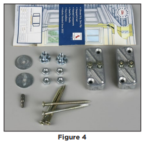
Follow the enclosed brochure Cable Support Kit Installation Instructions Straight Line Clamp. The T-nuts at the top of the unit, and the washers and nuts at the bottom have already been installed at the factory. The cables have been threaded and the free ends stapled to the top of the head board. Remove the staples to free the cable ends, then follow the instructions to position the clamp to the wall.
Check that the unit is plumb, level and square.
Adjust shims as needed. Drive 10d finishing nails or #8 x 2 ½” flat head screws through the plywood seat board, the shims (if present) and the rough opening framing member at maximum of 16” on center across seat board. Repeat across the head board. Drive fasteners through the plywood jambs, remaining shims and rough opening framing member in both jambs.
Remove the temporary support and jack from under the seat board. Check the seat board for level. If adjustment is required, reinsert the temporary support, then turn the nuts on the threaded rod at the bottom of the unit to adjust the seat until level. Do not cut the threaded rod extending from the bottom of the unit to allow for future adjustment of the cable system nuts.
From the exterior, insert backer rod into the gap between the head and jamb boards and framing members. Seat board will require backer rod only if shims were needed and a gap exists. Apply exterior-grade sealant between window plywood boards and rough opening framing members on all four sides of window unit, completely covering any backer rod present. Smooth sealant bead and remove excess.
From the interior, apply low-expansion foam insulation around the perimeter between the window plywood boards and the rough opening framing members starting at a depth of 1” on the inside of the backer rod to allow for expansion of the foam and fill remaining void to interior surface.
Two pieces of trim are included with this window to cover the void between the vinyl window and the plywood jamb boards (Figure 5). Cut trim parts to fit available space properly. Align trim profile vertically along plywood jamb board and against vinyl side.

Fasten to plywood jamb board using finishing nails (not supplied). Apply and fasten any additional interior trim (not supplied) over the exposed edge of the plywood boards.
*Instructions last updated 8/1/2015
